 Earth
Air Fire and Water
Earth
Air Fire and Water
The Pharmageddon Herbal
Chapter 5 Part 3.
Dehydration
The Owner Built Dehydrator 5.33
A well built dehydrator is an investment. The use of which, is
classified as agricultural processing. If research and marketing is done
correctly, then 0.5 ha coupled to a dehydrator, will produce a good family
living. How this is done will be explained later in the text. With the
exception of the fans and control gear to vary air volume*,
everything else may be built from reclaimed materials.
*
In some cases such fans can be salvaged from a vehicle radiator and with the addition of a thermostat and a couple vehicle batteries wired in parallel would prove equal to the task. So please remember the instructions are not set in concrete, what matters for the self builder is to get the broad idea of what is needed and then proceed according to ones means and capacity and your success is assured.Putting it all together 5.34
The following sections include construction notes and building plans for
a Prototype 12 m� Hybrid Forced Draught Tunnel Dryer; which includes all of
the principles previously discussed. The measurements are given in
millimeters.
When the dehydrator is built it will need to be prepared for its commissioning trials. Instructions are given as to procedures to be followed to prepare the dehydrator for operational use.
Specifications and Construction 5.35
Type � Forced Draught Tunnel Dryer.
Heating Mode � Hybrid. Solar air preheat/Solid fuel.
Air Circulation � 2 x 350mm Axial flow fans. Industrial rated. They must be able to sustain 10 to 12 hours continous running at 60�C and be moisture and corrosion proof. The fans and blades should be examined at regular intervals with particular attention paid to the impeller and its tips. At the first sign of corrosion or pitting then a further coat of protective paint should be applied.
Solar Collector - Roof mounted solar air panel. The panel approximates 15 m� and it�s angle will vary according to its latitude.
Furnace � A modified 200 litre steel storage drum half lined with fire brick.
Tunnel Dimensions � 6000 x 1050 x 2500 mm.
Heat Plenum Dimensions � 6000 x 500 x 2500 mm.
Capacity � 6 x 1m� trolleys each carrying 11 x 1m� drying trays. Maximum loading 300kg.
Load and Unload Ports � Outward opening air tight split doors.
Air flow Control - There are two ambient air inlets; one on entry to the solar air panel, which should be fitted with a sliding damper, and one at the air return duct, which should be fitted with an adjustable louvre vent. The dehydrator exhaust vent must also be fitted with an adjustable louvre vent. By manipulating the vents and the fan air volume controls, a wide range of dehydrator climates can be created by altering air speed, temperature and humidity.
Recommended Fuel - Wood. Hard wood is better than soft, having a higher energy output, and kilo for kilo yields less tar products than soft wood. That means less flue cleaning and less risk of flue fire.
The Building Plans � Figure 5.35A
Figure 5.35B
Figure 5.35D
Construction Notes 5.36
The Storage Drum Furnace
1.Flue bends or elbows must be kept to a minimum.
2.A horizontal flue run should not exceed 6m in length.
3.A horizontal run must rise 4 cm per meter run; minimum.
4.The flue outlet must extend at least 60 cm above the roof.
5.A revolving cowl should be fitted to eliminate back draught.
6.Cleaning ports must be included at every flue bend.
7.Dampers will be needed, to increase or decrease burn
The Solar Roof
The solar roof angle should match the latitude in which the dehydrator
stands. For locations in the Northern hemisphere, the roof angle should face
south, and for the Southern hemisphere, north. The rear wall and packing
plates should be altered to match the solar roof angle to latitude.
The solar roof should be constructed in situ, this circumvents lifting and positioning problems. All joints should be stopped with a flexible waterproof filler. The roofing iron should be etched or primed, and then painted with good quality matt black paint.
The absorber plate film cover should be stretched sufficiently to remove any wrinkles. If it is over stretched it will split very easily. If the film is of poor quality, then ultra violet rays will render it brittle, and it will not last more than one season. Secure the film to the outside of the solar panel with weather proofed battens. The fixing screws should be lightly greased before driving them home.
Timber Construction Materials
Exterior and interior timbers will be subjected to constantly
fluctuating temperatures and humidity; therefore, well seasoned timber will
minimize the problems of shrinkage, warping and splitting.
Interior Linings
The ceiling in the heat plenum and drying tunnel should be lined with
heat resistant board, and the joints stopped with a fireproof filler. The
heat plenum access port must also be faced with the same material. The
tunnel entrance and exit doors must be made air tight with sealing strips.
Exterior Fittings
The louvres and solar roof vents should be covered with insect netting
to prevent access. The furnace housing must be insulated to prevent
excessive heat loss. Provision must also be made for rainwater guttering.
Air Circulation Equipment
All wiring must be rated for the load it must carry, and be enclosed in
conduit, which is then chased flush with the wall. The power control gear,
ie, fuse box and master switch, on/off switches and fan speed controls,
should be mounted in a convenient place on the exterior of the dehydrator
and suitably protected from the elements.
Instrumentation.
Three hygrometers are required. One should be mounted on hinges on the
interior of the exit doors, and one on the interior of the inlet doors (see
Figure 5.36A), whilst the third hygrometer may be mounted on the exterior of
the dehydrator, around 1.5 meters above ground level. Ensure that the
hygrometer is not mounted over a dehydrator hot spot, because that would
distort the atmospheric air readings.
Figure 5.36A Hygrometer Mounting
When the dehydrator is in use, the hygrometers should be set parallel to the air flow; and when a reading is required they may then be pulled to face the perspex window, by means of the slide. When marking out the doors for the hygrometer mountings, care should be taken to ensure that free movement is not impeded by the dehydrator trolley trays. It will also be found necessary to extend the wet bulb water reservoir so that it does not become exhausted during operations.
Miscellaneous Points
1. The inlets for the furnace and heat plenum fan should be strengthened
by a reinforced concrete lintel, to bear the weight of the wall.
2. The concrete ground slab should be sized so that all weather protection may be afforded for all of the dehydration procedures.
3. An extra power point included in the electrical control box will prove to be useful when inspecting the heat plenum or carrying out maintenance work.
4. Under no circumstances should electric wiring pass through or over the heat plenum.
5. Any fittings or wiring that occupies drying tunnel space must be flush with the wall or ceiling, so as not to obstruct the free run of the drying trolleys.
6. A further refinement could include lighting for the dehydrator tunnel. The lighting should be enclosed, moisture proof and set flush with the wall or ceiling.
Operation of the Air Flow Vents 5.37
If the dehydrator is to function correctly, it should be airtight,
except at those vents which are in the open position. There are four vents.
One which is a sliding or flap vent, which controls the air flow into the
solar roof panel and the other three are as shown in Figure 5.35C.
Constant Rate Air Flow Pattern. Figure 5.37A
The dry bulb temperature of the atmospheric air will increase as it proceeds along the interior of the solar roof. When the air passes into the heat plenum, it will be further boosted to operational temperature. At this stage the wet bulb temperature will remain constant.
The air is then fan sucked into the dehydration tunnel. As it proceeds along the tunnel, the wet bulb temperature will increase and the dry bulb temperature will decrease, ie, heat and moisture are interchanged between the air and the drying material.
A close watch should be maintained on the exhaust air hygrometer. If the air approaches saturation, then the air speed and volume should be increased. Saturation temperature for a given condition may be read off the psychrometric chart.
Falling Rate Air Flow Pattern Figure 5.37B
During the falling rate period, the rate of evaporation starts to fall away. The wet bulb temperature will steady, and the dry bulb temperature will start to rise.
Therefore, the air will carry much unused heat. Fuel economy may then be practiced by recirculating the air. The furnace can be damped down and the temperature maintained at operational level by opening the solar roof vents, if atmospheric conditions are favorable. If the temperature starts to climb rapidly, then cool air may be introduced via vent �C�.
When the wet bulb temperature starts to approach saturation, then open vent �A�. Changes in air condition do not happen instantly, it may take 4 to 5 minutes to achieve the balance sought. Therefore, practice is the path to competence.
Cooling and Conditioning Air Flow Pattern. Figure 5.37C
In this configuration, the dehydrator air may be promptly cooled so that the drying temperature is not exceeded. However, as the operators skill increases, this will cease to be necessary. In normal circumstances when herbal material is removed from the dehydrator, the conditioning procedure could take up to 8 hours. By using this pattern, the material may be quickly conditioned in situ. When operations cease, the operator may vent the dehydrator and quickly reduce the temperature to ambient, without condensation. When conditioning or venting, remember that the furnace must be out.
The Importance of Turbulent Air Flow
A turbulent air flow is absolutely essential to good dehydration
practice. Unless the air is well mixed, much heat energy will be lost, the
drying time will be unfavorably extended and wet spots will be endemic.
If the fans are set parallel, the air will find the easiest way through the dehydrator, thereby creating numerous wet spots. Always position the fans at right angles to each other and problems can be promptly eliminated by strategically placed baffles.
Commissioning the Dehydrator 5.38
On completion of the dehydrator, the electrical circuits and control
gear should be tested and any problems rectified. It is advisable to wait 4
or 5 days before attempting the first firing, otherwise damage could occur.
The doors and heat plenum should be opened to allow the structure to air.
Assemble sufficient fuel for an eight hour burn. Select a fine clear day for the initial firing and proceed as follows;
1. Check and note the ambient air temperature and humidity.
2. Ensure that the heat plenum access port is secured, close the doors. Open the solar vent and louvre �A�. Switch on the fans and set them at half speed.
3. Wait for 30 minutes, then check and note the drying tunnel temperature. Then repeat the process with the fans running at top speed for 15 minutes.
4. Set the vents for air recirculation and run the fans at half speed for 15 minutes, then check and note the drying tunnel temperature. Ensure that the solar vent is open. Repeat with fans at top speed.
A simple comparison of the readings obtained will give an indication of potential heat gain from the solar roof. Obviously, isolated hygrometer readings at a single ambient temperature will not confer any degree of accuracy. If maximum dehydrator efficiency is to be obtained, then a series of readings must be taken across a range of atmospheric conditions.
5. Set the vents for the constant rate air flow pattern.
6. Light the furnace, and with the fans running at half speed, slowly raise the dehydrator temperature to 40�C.
Remember the SHC of the dehydrator and its furniture, it will take around 15 to 20 minutes to reach operational level.
Do not attempt to rush Step 6. A fast fierce initial firing could cause undue shrinkage and structural damage. When the working temperature has been reached, then the operator must maintain the temperature for a period of two hours.
During that period the atmospheric temperature can markedly fluctuate. The object is to maintain a steady dehydrator temperature, irrespective of the raw atmospheric conditions. The means are as follows;
A. The amount of fuel burnt.
B. The damper controls on the furnace.
C. The fan speed controls.
D. The adjustable louvre vents.
On completion of 2 hours at 40�C, increase the fuel loading and steadily raise the temperature to 60�C. Maintain a steady 60�C for a further 2 hours.
7. Finally rake the fire from the furnace and with fans running at top speed for 20 minutes, vent the dehydrator to the atmosphere.
8. Close down the fans and switch off the power. Shut the dehydrator vents and doors and leave overnight.
9. On the morning following, the dehydrator should be carefully examined, inside and out, with particular attention being paid to the heat plenum and all points where block-work and timber meet. Any gaps should be made good with appropriate filler and allowed to set. Finally, test the fans and the electrical control gear.
The dehydrator may then be considered commissioned and ready to undergo drying trials. The commissioning procedures should also be taken as valuable training time for the operator, and extensive notes taken and observations made.
Preparation for Drying Trials 5.39
The information compiled during the commissioning procedures, will make
obvious that the air condition in a fully loaded dehydrator, will vary
markedly between inlet and outlet. Conditions at the exhaust end will be
cool humid, and at the inlet warm dry.
For dehydrators up to and including 6 m in length, the unequal drying, due to relative position in the tunnel, is compensated for by air recirculation during the falling rate phase. This produces a great saving on labor and fuel.
For drying tunnels over 6m, then better results may be obtained by resorting to counter flow methods, ie, a trolley load of finished material is removed from the warm dry end of the dehydrator and a trolley of fresh material is introduced at the cool humid end. The term �counter flow� is derived from the fact that the trolleys progress through the dehydrator against the air flow.
For such materials as elder berries, hips, haws or seeds, best results are obtained by adopting a parallel flow method.
When moving air changes direction, or strikes an obstruction, swirls and eddies are created. Generally speaking, the higher the velocity, the greater the disturbance,; consequently, the velocity at the floor and roof levels may be greater than at the center.
Turbulent Air Figure 5.39A
Such disturbances are necessary for a good air mix, but they can also cause wet spots in the drying material.
Wet spots are eliminated by the use of air baffles, which are simply pieces of board or canvas which are placed at the relevant points in the tunnel. Incorrect or overloaded dehydrator trays can also cause problems.
It should be remembered that the drying herb becomes progressively lighter, therefore, the air velocity should not be greater than required for drying, lest the material should be entrained and deposited at the far end of the dehydrator.
Approximately 200 kg of fresh herbage will be needed for a single drying trial.
Material that approximates fresh herb should be foraged. It is then chopped and loaded onto the drying trolley trays. The trolleys should be numbered consecutively on entry to the dehydrator.
The Drying Trail 5.40
The drying trial is conducted on a batch/load basis, ie, the trolleys
are not progressed through the dehydrator, when the exhaust end trolley is
dry, the dehydrator is then unloaded. Proceed as follows;
1. The dehydrator is fired up to working temperature, the trolleys are loaded and numbered. When the dehydrator is operational, trolleys are run into the tunnel in consecutive order.
2. When the loading has been completed and the doors closed, the time and conditions are logged, and the trial commenced. Every 15 minutes hygrometer readings should be made and logged. An example of an operators log sheet is as follows;
Hygrometer Data and Log Sheet. Figure 5.40A
Key to abbreviations.
1. ATH = Ambient temperature and humidity
2. DW = Dry weight
3. ETH = Exhaust temperature/humidity
4. FW = Fresh weight
5. ITH = Inlet Temperature and Humidity
6. OT = Exhaust Temperature and Humidity
Good records are essential; inefficiency is the price of neglect. Analysis of records will give the operating efficiency of the dehydrator and will allow accurate production costings per batch/load. A skilled operator will be able to increase overall efficiency by some percentage points, which, when totaled at seasons end, will prove to be quite substantial.
3. When the trolleys are unloaded each tray should be examined for wet spots and its position on the trolley noted. That information indicates where to place an air baffle in the tunnel.
Figure 5.40B
Fan speeds cannot be used to eliminate wet spots because a reduction in volume will interfere with optimum moisture uptake. The baffles will in turn, modify air flow patterns, so a small amount of experimentation will be required. Two or three canvas strips hung from the tunnel ceiling should be adequate. The leading edges should be weighted and clear of the loaded top tray.
4. In the normal course of events the material would be conditioned in situ, prior to unloading the dryer. If the material is to be further processed immediately, then the conditioning process is unnecessary. If, however, the material is destined for storage, then conditioning is essential to avoid leaf shatter. Proceed as follows;
A. Close down the furnace and shut the solar air vent.
B. Open louvres �A� and �C�, and run the fans at half speed
for 35 to 45 minutes.
The material should then be dry but not crisp.
Storage and Fumigation 5.41
The twin problems of preservation and storage are as old as our species.
For dried herb and other vegetable matter, most current solutions are less
than optimal. Therefore, it is not until the extraction stage that plant
drugs can be considered truly stable.
If correctly stored, dried herb will maintain viable quality for up to 9 months,. Thereafter, deterioration is rapid, although the herb may appear cosmetically sound. During that time, there are various factors that contribute to deterioration, and may be found under the following headings;
A. Light, both Natural and Artificial. A common example would be the bleaching of drapes and fabrics by sunlight. With herbs, chlorophyll is the first substance attacked. This may be observed as a progressive bleaching of the material, e.g. examine the jars in the kitchen spice rack.
B. Heat and Humidity. Stored material should not be exposed to temperatures higher than those used for dehydration, lest damage to secondary metabolites occur. High humidity can also reactivate herb enzymes. The plant enzymes reach peak activity between 30 and 35�C, and loss of medicinal potency is rapid. The temperature and humidity fluctuations experienced in any 24 hour period may also trigger attack by molds or bacteria.
C. Insects, Winged or Crawling. Insect infestation is the most common of all storage problems, and dried herb is a good source of food and shelter for numerous species. The spread is rapid, causing much economic loss, and compounded by transmission across borders.
Governments maintain a phyto-sanitary service, contaminated shipments are fumigated with highly toxic substances, such as ethylene oxide or methyl bromide, traces of which are found on, and in the treated material. In such circumstance the organic grower�s efforts have been in vain. Many of the problems may be avoided at the pre-clean stage prior to dehydration. Particular attention should be paid to the undersides of leaves, where clusters of insect eggs may be commonly found. Seeds, such as fennel or coriander, can be particularly troublesome. Certain types of flowers, such as Marigold, can also be a problem. Growers would do well to make themselves familiar with the life cycles of insects, which are peculiar to the materials, and region, in which the herbs are grown.
D. Avian and Rodent. Damage from nests and burrowing can be considerable, with high levels of contamination from feathers, hairs, excreta, mites, lice, maggots, etc. Those problems are the precursors of serious bacterial problems. It may be supposed, that the bactericidal properties of herb would prevent such a problem, however, the active principles are fixed by the drying process in the interior of the herb. If dried plant material is cultured on a nutrient jelly, such as agar, in many cases colonies of pathogenic bacteria, such as Salmonellae, will multiply rapidly. Undoubtedly birds and rodents are the primary vector.
Major problems may be avoided by common sense hygiene. The storage area should be sound, weather proof and insulated, so that a cool dark environment is created. Windows should be blacked out and insect screens fitted at points of entry. Interior linings should be smooth and washable, and all joints and cracks sealed. Adequate ventilation must be provided for.
Herbal material should be packed in cardboard or double lined paper sacks, which should not stand directly on the floor, but stacked on slatted shelves or racks. All materials should be turned and inspected at regular intervals. A stock rotation system should be put in place and strictly maintained.
Problems of cross contamination can be avoided by common sense; e.g. Valerian root and Lavender, stored next to each other, would cause problems, as would the re-use of packaging for different specie. Vacuum cleaning should be resorted to on a regular basis. Remember you are protecting a high value product.
At the first sign of a problem, and certainly never less than every two months, a thorough fumigation should be carried out. In tropical areas the old British Colonial Services used ground chilli pepper, powdered cow dung, or a combination of the two. Small charcoal burners are used and the powdered fumigants are sprinkled on the burning charcoal. Such substances work by suffocation and are not effective against eggs and pupae.
As an alternative, pyrethrum based mosquito coils may also be used. Use one burner per 4 m� of space. Light the burners, retreat and seal the storage area. Leave for one hour and then ventilate the area. The usual fire precautions should be taken.
Preparations for Further Processing 5.42
Operations under this heading may be classified as size reduction and
screening. If the small scale grower wishes to market dried herb, then they
must seek to enter a distribution chain at the wholesale or retail level.
Penetration at lower levels will render the operation marginal.
Size Reduction 5.43
As an item of commerce herbal material may be found in four basic forms,
which are as follows;
1. In the cut form. This refers to the method by which the material is handled. The size of the cut is determined by its end use. If the material is for the purpose of infusion, it will be cut into pieces between 3 and 5 mm in length, smaller particles are then sieved (screened) out. The trade term is �Cut and Sift� (C/S).
If the material is to be sold in the form of tea bags, then the herb must be cut much smaller and be of a uniform size, to ensure a smooth consistent flow through the tea bagging machine. The trade term is �Tea Bag Cut� (TBC).
If the herb is to be used for flavoring purposes, then the initial cut will have already been made as part of the dehydration operation. For culinary purposes, the trade term is �Rubbed�. This is taken to mean screened herb less stalk.
2. Chipped or Rasped. This form of size reduction is limited to the harder materials, ie, roots, barks, and the woods, and is usually a preliminary stage prior to granulating or powdering.
3. Ground. This is the most common of the size reduced material. It is the easiest to prepare and produces the least amount of waste. The tailings, or gristings, are simply added to a subsequent operation. Different particle sizes are specified according to the end use. The shelf life of ground materials is considerably less than that of material in its whole form. This is due to the great increase of exposed surface area.
Do not store ground materials, always fresh grind, as needed. The presence of insect eggs, which may hatch, leads to a condition known as �webby or stringy�. The terms are descriptive with the material hanging together in clumps. Such material should be rejected.
4. Whole. This form is encountered in great variety. As seeds eg,. Coriander, Dill and Fennel; as pods or capsules eg, Vanilla, Capsicums, etc. Whole materials are also found which are cut to specific lengths, such as Cinnamon, quills or liquorice root. Flowers or petals are also marketed whole, as are various fruits, such as Hawthorn berries, Elderberries and Rose hips.
Methods of Size Reduction 5.44
Cutting. Depending on the rate of output required, any of the following
methods may be used; scissors, knife, domestic bowl cutter, chaff cutter,
mulcher, modified ribbon mower or a shear mill. The shear mill is precision
engineered, very accurate, with a high output. The expense involved would be
difficult to justify for a small scale grower. Much more suitable would be a
second hand chaff cutter, or for smaller quantities, a ribbon mower powered
by an electric motor.
Chipping or Rasping. This operation is usually a preliminary to grinding, it�s purpose being to reduce the material to a manageable size that will pass through the throat feed of a grinding machine. For small batches, one may employ a handsaw or a planing instrument, if working woody materials such as quassia. For larger outputs, a motorized mulcher will meet the needs of a small scale grower. The mulcher is also quite efficient in handling dried root. Do not attempt to put fresh material through, the damage is unacceptable. For large through-puts, a disintegrator is used. The disintegrator is essentially a large, heavy duty fixed hammer mill.
Grinding or Powdering. The traditional methods of reducing a solid to small particles was by crushing and shearing eg, the mortar and pestle, or by mill stones, alternatively, the material was reduced by impact or pounding. The only thing that has changed is the technology used, which has resulted in a reduction of labor and an increase of output.
All milling operations produce heat, some more than others. Excessive heat will damage the herbal material, accordingly, some methods are unsuitable, eg, the modern stone or plate mill, that work on the crush and shear principle, with speeds between 600 and 800 rpm and outputs ranging from 50 to 1200 kg per hour. There are many types of grinding mills, each being designed for a specific purpose. For the purpose of herbal manufacturing, the simplicity and versatility of the hammer mill cannot be matched.
The Hammer Mill. Figure 5.44A
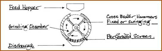
The material is reduced by impact and shear. The lining of the grinding chamber is usually corrugated to ensure multiple deflections of the material back into the hammers path. They operate at speeds of up to 3600 rpm. The schematic illustrates the general principle upon which the hammer mill operates. Particle size and shape is controlled by interchangeable perforated screens. The perforations are available in a variety of shapes and sizes. By selecting an appropriate screen and controlling the rate of feed, an operator can produce cut, or tea bag cut herb, as well as particles of a given size.
The rate of flow to the grinding chamber must be carefully controlled. If the rate is too high, then screens will clog and sufficient heat for the ignition of the material can occur. If the rate is too slow, then a large proportion of undersized particles will be produced. The trade term for those particles is �Fines�. For C/S and TBC, obviously, the fines must be screened out.
Sieving or Screening 5.45
The purpose of the sieve is for separation and cleaning, or for particle
classification. As such, they represent indispensable equipment for herb
farm or laboratory. Originally, sieves were designated by the number of
apertures per linear inch, therefore, it is also necessary to specify the
wire diameter to be used. For the purpose of uniformity of particle size,
each sieve had a fixed relationship to the sieve that preceded or followed
it. Accordingly, each sieve was allocated a number, which set its position
in a series. The British series of mesh numbers was based on Standard wire
gauges, whilst the U.S. system was based on the number of apertures, with
the ratio of 2:1 between sieves; however, each system used a mesh number
that was the approximate mesh in each system. Fortunately the ISO has
evolved a standard series of sieves, based on the metric system.
Standard Sieves Table 5.45A
|
Standard I.S.O. |
Aperture Standard |
Wire Diameter |
Mesh Number |
Remarks |
|
8.00 mm |
8.00 mm |
2.07 mm |
2� |
|
|
5.6 mm |
5.66 mm |
1.69 mm |
3� |
|
|
4.00 mm |
4.00 mm |
1.37 mm |
5 |
|
|
2.80 mm |
2.83 mm |
1.01 mm |
7 |
|
|
2.00 mm |
2.00 mm |
0.900 mm |
10 |
|
|
1.41 mm |
1.41 mm |
0.725 mm |
14 |
|
|
1.00 mm |
1.00 mm |
0.580 mm |
18 |
Coarse |
|
0.710 mm |
0.707 mm |
0.450 mm |
25 |
Medium coarse |
|
0.500 mm |
0.50 mm |
0.340 mm |
35 |
|
|
0.355 mm |
0.354 mm |
0.247 mm |
45 |
Medium Fine |
|
0.250 mm |
0.250 mm |
0.180 mm |
60 |
|
|
0.180 mm |
0.177 mm |
0.131 mm |
80 |
Fine |
|
0.125 mm |
0.125 mm |
0.091 mm |
120 |
Very Fine |
|
0.090 mm |
0.088 mm |
0.064 mm |
170 |
|
|
0.063 mm |
0.063 mm |
0.044 mm |
230 |
|
|
0.045 mm |
0.044 mm |
0.030 mm |
325 |
|
Laboratory sieves are precision instruments, as such, a complete set will prove to be expensive and totally unnecessary. For precision work the following mesh numbers are recommended; 18 - 25 - 45 - 80.
For work on the herb farm, sifting mesh has a wide variety of applications for cleaning and grading of materials. The following mesh numbers are recommended; 7 -10 - 14 -18.
The requisite mesh should be purchased and 1m x 1m sieves constructed. They should be robust with strengthened corners to withstand constant use. The sieves may be used in nested form or individually as shown;
Farm Sieves. Figure 5.45A
With a little thought the operation can be mechanized in many ways.
Sieving is dirty, dusty work. A face mask is required. Air classification or winnowing can be used with advantage, for seed.
Library
Pharmageddon
Herbal Block Index
![]()